STEAM CITROËN
The Project in a Nutshell
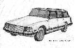
Almost no one drives a steam car. Practically no one in this country drives a Citroën. Certainly no one drives a steam Citroën! But if there was any fear in ploughing fresh ground, it was not in the heads of Mike Ormiston or Karl Petersen when they began the project of constructing this vehicle.
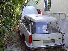
Mike wanted to have an environmentally gentle station wagon in which to tour the Southwest with his teenaged daughters. The concept of treading lightly on the land following the philosophy of the American Indian was foremost in Mike's requirements, and a steam car with its naturally low pollution levels was the only technology which was suitable. The vehicle's appearance was also of concern. It should not look like its smog emitting cousins--even like a stock Citroën. Otherwise it should be fairly compact, reliable, and interesting. Mike was confident that with the proper effort even a one-off steam car would probably be quite reliable. Mike had asked Dick Smith to put together a car which met these needs, and Dick had tried to convince him that this was too much to hope for on a reasonable budget. Mike's next step was to propose the same idea to Karl Petersen. Karl suggested that, although a fair amount of regular fiddling would certainly be part of the adventure, local machine shops or refrigeration mechanics could provide the necessary work to repair or replace any part of a system if a comprehensive manual and sets of drawings were provided. Thus, in April 1973 the project was begun in earnest. Karl opened a project account, leased a quarter of the Santa Ana machine shop of John Peterson and brought the car in to strip down for reconstruction. A stripped Citroën is a very strange skeleton since virtually everything comes off the unit body. Power plant design work having been completed in advance, the body construction proceeded while the mechanical details were constructed and assembled.
Looking forward to a less hectic lifestyle, Mike had sold his radiology practice and was able to fund the project with a budget of $20,000. This was to include both building the power plant and rebodying the car at the same time. Karl pointed out that either the body or the power plant could consume such a budget, even in the early '70s. Mike insisted that both be started and developed in parallel, eventually consuming $30,000. All work stopped when Mike's accountant insisted that the project was not a suitable re-investment of capital and the IRS dried up any chance to finish the project although the work was 90% complete.
The Car
In selecting a car for conversion, Mike noted the simplicity of the Valiant and its cousins, largely due to the reliable slant-six engine. But, the engine, the Valiant's stong point, was to be removed. Mike agreed to Karl's suggestion of the comfort and flexibility of the Cit, especially appealing for long distance touring. Inquiries went out for a suitable car, and a clean fresh 1968 wagon was found in Arizona with a damaged engine. Perfect.
While the search was on for the wagon, a Citroën sedan was instrumented in Santa Ana for air flow and pressure tests to determine the optimum location for the radiator. Air pressure was weak from the leading edge of the hood all the way across the windshield and over the roof. The highest pressure point was directly under the nose of the car. Although no other auto maker placed their air intake at this point, this was exactly where the air intake duct was located on the stock Citroën. The lowest pressure point on the car was just at the rear of the engine compartment, under the driver's feet. Since there was no necessity to place the radiators at the front of the engine compartment and feed hot air over the equipment, the radiators were placed in a bank at the rear of the compartment. The entire compartment was fed as a plenum with ram air from an inlet duct behind the front bumper, and the radiator air outlet was ducted by the cowl at the rear of the engine compartment, right out the bottom by the drivers feet. This way, the hot air from the radiator was kept out of the engine compartment.
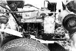
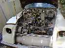
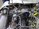
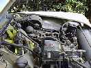
The stock engine bay was quite large. The stock spare tire location was in front of the stock radiator with the drive line under the radiator and the engine to the rear. In the even of a front-end collision, this extra length provided nearly three feet of crush area before the radiator was affected. With all the IC equipment cleared out, the space was enormous, especially when compared to a Valiant. Karl and the mechanics took one another's pictures while laying full out under the hood.
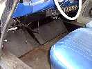
The stock fuel tank was in a box section under the rear seat while the stock muffler was nestled into a recess under the front seat. The front seat recess made enough space to install a water tank similar to the gas tank. The front floor originally had a substantial restriction where the rear of the engine came all the way back to the face of the dash. Although this was neatly carpeted, and the floor was flat without a transmission hump, it left separate footwells for the driver and passenger. With the new radiator position, the engine bump was deleted and the floor became flat all the way across. The footroom is so extensive that it gave an odd feeling, like not wearing seatbelts when you're used to them.
The Engine
Karl had been working actively on steam car hardware since 1966, and had built a number of engines and steam systems for cars and boats, often jointly with Dick Smith, in the seven years leading up to 1973. After directing a year of steam engine development at Edwards Development Center in Santa Ana, Karl designed an engine based on the most highly developed bash-valve uniflow principles of the time, relying on contributions from Dick Smith and Pete Barrett, the front runners of steam car development in Southern California.
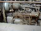
The basis for the engine was a Mercury Marine roller crank, rods and pistons which normally ran in a 62 cubic inch four cylinder outboard. A lower block and crankcase were fabricated from aluminum plate and finished machined in Peter Barrett's shop by Phil Barrett and Karl. Nitrided cast iron diesel liners were ordered to fit. These cylinders were bored with uniflow exhaust ports. Built-up heads with inlet passages feeding three disc bash valves were brazed assemblies of mild steel individually mounted with studs into the crankcase.
Pins on the top of the pistons to operate the bash valves were fabricated from Honda 90 exhaust valves mounted flat end to the piston and secured with socket head cap screws. Instant adjustment in valve opening timing was not possible, but shimming the heads or the pins allowed tuning for development or to compensate for wear. Initially no modifications were made to the Mercury aluminum pistons, although this kind of engine operates best at temperatures which would soften the aluminum, and laminated ceramic-iron composite tops were planned after initial road testing.
The valves were set on the dyno at Smiths before mating with the transfer case.
Rotary Plate Starting Valve
A double acting Stephenson link engine like the Stanley or Doble use will start smoothly in either direction, but a bash valve engine has a very narrow admission opening from the bash valve and a punch with each valve opening. It will operate well in both directions, though, if the porting is symmetrical. With such an engine, two methods can be used to start the engine and get good low speed torque. On an IC engine conversion, you can retain the starter, gearbox and clutch. Then you start the engine with the starter, but you have to let it idle, and use the gears.
In this case, a rotary steam distributor valve was chosen to start the engine in the proper direction and pass steam for a long stroke to provide good starting torque without changing gears. This valve was developed by Dick Smith for his Merc conversions after the rotary sleeve valves proved to be damaged too frequently by debris in the steam system. Compressed air starters on oil engines such as Diesels also provided inspiration if not a suitable method for handling hot steam.
As a rotary plate valve based on the concept of the Serpollet throttle--a moveable plate covering the exit hole from a steam filled chamber. The valve plate and the exit hole plate were lapped flat to provide a practical seal to shut off the steam. Smith's rotary version had a disc with a notch in one side to pass steam through 1/4" tubes to the heads in the desired sequence. Since the tubes were small and long, the impulses from the engine compression played ping pong with the starting valve steam. Beyond a few hundred rpm, the timing canceled and the starting valve had no further effect. As the engine speed dropped, the starting valve came in again.
Reversing the car required spinning the control shaft on the valve in the reverse direction before opening the throttle, and the engine would go in reverse just as easily as it forward. Just how to conveniently spin the control shaft was a question which has no simple answer. Attaching a small, reversible electric motor to the shaft and powering it briefly before starting off was a straightforward solution. This was esthetically annoying, because it was one more electrified auxiliary to a basically non-electric vehicle. A knob on the dash which required a spin to change direction was a cute idea, but it would spin at engine speed whenever the engine was turning! Not as tricky to operate as a choke knob, but the safety aspect removed it from consideration. Since the gearshift was retained to shift the engine in and out of engagement, so that it could be run without jacking up a wheel, the gearshift could also be used to spin the shaft through an ingenious clutch arrangement, but that would have made an electric motor look like simplicity itself.
Steam Generator
A long drum monotube unit wound from iron pipe was economical and simple to build. The relatively low efficiency of this radiant/conductive heat transfer coil could be made up by a finned element in the exhaust if economy demanded. A pressure-atomising oil burner nozzle and electric blower created the flame. The nozzle ide bypass which allowed a 4:1 turn down ratio. Maximum burner efficiency was achieved at full firing, and lower trim rates reduced fuel only, so excess air was pumped by the blower. The fuel bypass was operated by a valve on the overheat control, so it was only occasionally triggered. The overheat control operated by the expansion of the final pass of steam pipe through the center of the flame as it expanded in relation to an external caliper. A switch ultimately turned off the burner for safety overheat shutdown.
Power Train
No speed-change gearbox or two-speed rear end was used. Since the rotary starting valve and throttle gave smooth starts and the bash valves gave high speed efficiency, a fixed ratio chain drive was used. Three #40 roller chains transmitted power from the crankshaft to the differential. Don't roller chains make noise at high speeds? Yes, they do, but each of the three sprockets were offset one third of a tooth, cutting the vibration to one third and tripling the frequency of the noise so it was more easily damped by the oil in the chain case. Silent chain or Morse HyVo chain might have been quieter but would transmit no more useful torque and would be extremely expensive to install and service. This chain drive is installed in a aluminum case which carried the driveline towers with massive Citroën inboard disc brakes and was located directly between the front wheels.
In order to run the engine without driving the car, a rather typical multi-pin dog clutch was used such can be found in many manual transmissions. The small sprocket ran on brass bushings when running without load. This was operated from the car's original gearshift lever--pull to engage, push to run free.
Condensing
Bill Besler had emphatically stated that there is not enough frontal area on a car to put enough radiator to condense the steam from a steam car. In fact, he was talking about condensing the steam directly in a radiator placed on the front of a car like a barn door. He was right about the radiator application. Cooling a gas engined car with that 1903 technique might be laughed at today, but efficient radiators and pumped recirculating liquid coolant work quite well.
Spray condensing and cooling the resulting hot water by rapidly circulating it through a radiator allows a much smaller but hotter radiator to dump more heat into the air since the heat transfer from the water through the core is so much better than from fluffy steam. The spray was fed by a vane type circulating pump in this case. Water was drawn from the bottom of the feed tank where the pressure was the highest to avoid cavitation and the pumped water was made available to the feed water pump to help it avoid cavitation as well.
Auxiliaries
Driving auxiliaries has been problematical in most direct drive steam cars. When going fast, the units are pumping and spinning furiously, but when pulling a hill or on a slow parade route the pumping and fans and power are woefully inadequate. In order to keep up with requirements from three to ninty miles per hour, a variable speed drive (CVT) was used. Flyweights change the ratio of a variable belt transmission giving a speed boost to the auxiliaries at low vehicle speeds and dropping into direct drive at higher speeds. This concept had been used to drive marine generators, but according to Salisbury, the drive manufacurer, this was the first time the principle had been used in a vehicle. A similar drive was applied to Jim Crank's steam land speed record car to great success, even though other difficulties cropped up with each record run, even when Barber beat the 1906 Stanley steam land speed record with the car.
The circulating pump previously described fed a triplex double acting Cat brand pump. There are probably half a dozen suitable pumps for this purpose, and this one was selected based on ready availability of parts and service. It required external oiling of the pump rods, while unacceptable in a production car, was an excusable compromise in a one-off vehicle. A 12 volt Motorola alternator charged a large 12 volt battery. This gave a good spin to an auxilliary feed pump and a pressure-atomizing burner fuel pump.
An air conditioning compressor provided cooling for the
car and the Citroën hydraulic pump drove the suspension, brakes and
steering.
Photos in Late 1974 with Construction Nearing Completion
 |
 |
 |
 |
 |
Power Train Assembly Slideshow
SACA Meet in Boise, Idaho, 1979
 |
 |
 |
Just Out of Storage in 1998
 |
 |
 |
 |
 |
 |
 |
 |
Steps to Completion
Work having stopped before the showing of the car at the 1979 Boise SACA meet, some work remains to complete the installation of the developed system. This includes wiring, piping the steam run and rebuilding the engine steam exhaust manifold which was fabricated with soft solder by a plumber who could not believe that steam could get hot enough to melt soft solder. Apparently this is why there are plumbers and then there are steamfitters. A rear engine brace has not been installed, and the engine insulation and outer case have yet to be fabricated.
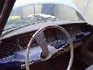
The body was painted and detailed, but the headliner and interior require completion. The appearance items require some renewal since the vehicle has been in dry storage since 1976.
Since the power train components performed well in bench testing, it would be intriguing to see the actual vehicle perform.
Experience of others with the MaxiSASS steam generator has shown it to have too high an exhaust temperature to be effective in a vehicle, especially when exhausting on the front tire. This could be changed out to a pancake coil monotube.
On View at the Kimmel Steam Shop in Berrien Springs, Michigan
 |
 |
 |
Please contact karlpete at yahoo.com for more information.
This page powered by ![]() Last updated on December 26, 2024. Copyright © 1999-2024 Karl A. Petersen.
Last updated on December 26, 2024. Copyright © 1999-2024 Karl A. Petersen.
