Steam Outlet Accessories
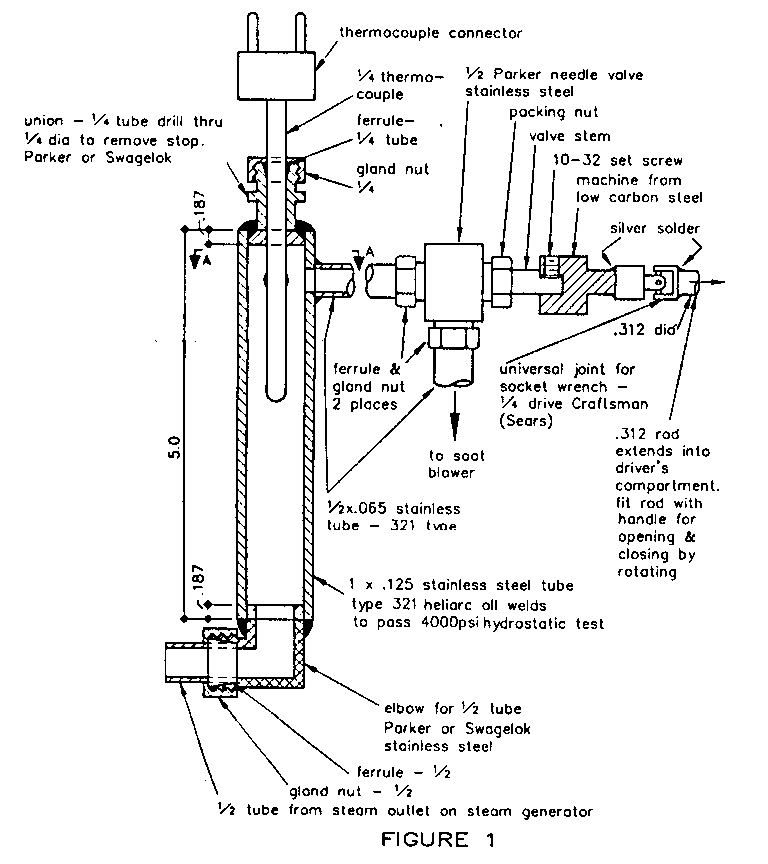
The steam outlet line needs to be equipped with the accessories described in this article. The steam outlet line leaves the thermostat and passes through the liner of the combustion chamber and the insulation to exit into the space outside of the steam generator. The steam outlet line should connect to the manifold shown in Figure 1.
The manifold is fabricated by welding, made from a 5" length of 321 stainless steel tube 1" in diameter by .125 * wall thickness. Drill two holes 3/8' diameter 90 degrees apart as shown in Section AA of Figure 1. Turn two disks 3/4" diameter, one with a .375* hole, the other with a .265" diameter hole. Chamfer the edge of the disk 'for ease of welding. Weld the disks into the tube; the disk with the 3/8" hole goes in the bottom as shown in Figure 1.
Next, weld two lengths of 1/2" diameter x .065" tube into the 1" tube as shown in Section AA. Select the length of the tube to permit connection to the throttle and the valve for the soot blower.
One of the problems in building a steam car is to fit a the components into the space available. Carefully plan where the best place is to locate the throttle and soot blower valve.
The valve used for the soot blower is made by Parker. It is for 1/2* tube and is a needle valve type made for stainless steel. An extension for the valve stem is machined from 3/4' diameter low carbon bar stock. A 10-32 set screw is used to lock the extension to the valve stem. The other end of the extension is silver soldered onto a universal joint for a socket wrench. Obtain the 1/4 ' drive universal joint (Craftsman) from Sears. The other end of the universal joint is silver soldered Lmto a length of 5/16' diameter rod. The length oi the rod should be such "hat the rod will extend through a hole in the car body at a location where the driver can reach the rod. The hole in the body should be equipped with a rubber grommet to stop noise and vibration. The original knob that comes on the valve is removed and mounted on the end of the 5/16" rod that extends into the driver's compartment. Thus the driver can open the valve and operate the soot blower when desired.
The bottom of the manifold should have a 1/2 elbow welded onto the disk with the 3/8' hole. Be careful to align the 3/8 openings by tack welding. If not aligned satisfactorily, break them off and realign.
The tubes and disk should be made from 321 stainless steel or, as an alternate, 347. If other 300 series stainless steels are substituted, you will have inferior welds because the carbides in the microstructure of the stainless steel will move to the grain boundaries. A brittle weld will result. The problem can be cured by heat treating the weldment after welding. An easier solution is to use the 321 or 347 alloys which have stabilizer which prevent the carbides from moving to the grain boundaries.
An attachment for a 1/4" diameter thermocouple should be welded onto the top of the manifold. The thermocouple mount can be made from a union by drilling out the stops for the tubing so that a 1/4' diameter thermocouple will pass through the Swagelok fitting on the manifold.

![]() Combustion
Chamber Drawing
sets are available. HP
Injection Pump
Combustion
Chamber Drawing
sets are available. HP
Injection Pump ![]()