Combustion Chamber Assembly and
Spinning Cup Burner -- Belt driven
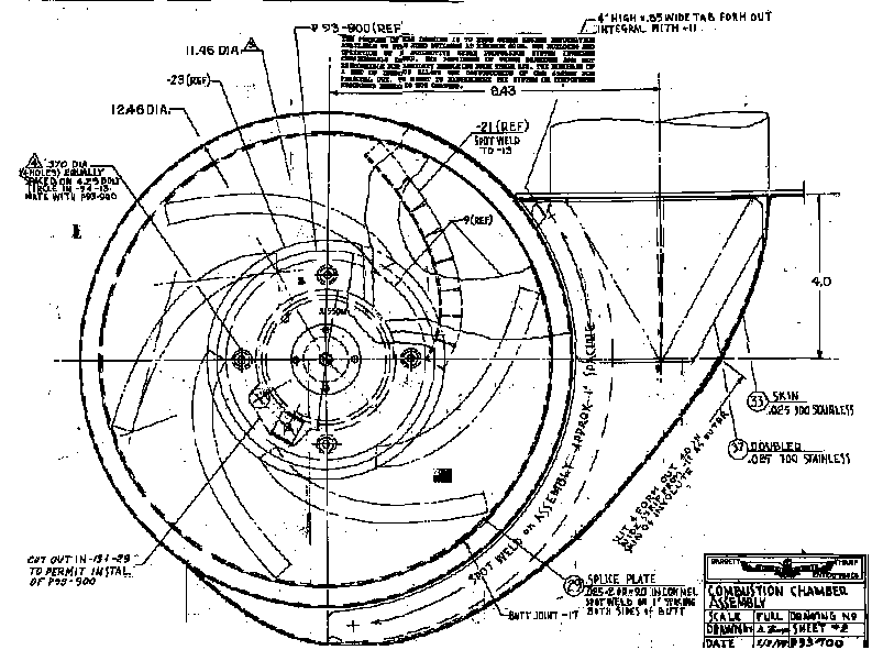
These drawings describe the sheet metal work necessary to build the combustion chamber. The combustion chamber drawings are available full size so they may be used as a pattern to cut out sheet metal parts. The parts are mostly spot welded together. Only one tig weld is needed. The combustion chamber contains guide vanes which causes the incoming air to swirl around to become thoroughly mixed with the fuel.

Drawings are also available for the belt driven spinning cup burner. The bearings of the spinning cup are cooled by fluid flowing through a cooling jacket. The spinning cup spindle must operate on top of the combustion chamber, a thermally hostile environment, hence the necessity for the cooling jacket. The spinning cup spindle is driven by a timing belt. This arrangement allows the electric motor to be placed in a cooler location. Originally the cup was driven directly by the motor, which was included in the cooling jacket. The change to the belt driven arrangement was made after a motor over heating failure. The spinning cup operates at 8000 rpm, so a larger selection of motors can be used with a step up ratio on the pulleys. Provision is available to renew the supply of oil to the spindle bearings. The combustion chamber and spinning cup has been working trouble free for 7 years.
There is a video tape available that shows step by step the construction or the sheet metal for the combustion chamber. The tape shows the proper sequence for making the spotwelds. If this sequence is not followed you will not be able to complete the assembly by spotwelding as the electrodes will not be able to reach the joints. The video tape is a big aid in building the combustion chamber.
![]() SpinningCupBurner
Drawing sets
are available.
Steam
outlet Accessories
SpinningCupBurner
Drawing sets
are available.
Steam
outlet Accessories![]()
This page powered by